



SA618F30-DZ : 1W 8 Dual Antenna Multi-Level Relay 8K Sampling Rate Audio Module Full-Duplex With ESD Protection
Output Power: 1W
Certification: Others
Type: Wireless Audio
Size (mm):39.3*24.0


SA618F30-C1 is an upgraded, cost-effective, high-integration, high-power full-duplex intercom module from NiceRF. It features a built-in high-speed microcontroller, audio Codec, echo cancellation circuit, ESD protection, high-performance RF chip, and amplifier. The module provides a standard serial port for communication, allowing users to easily configure parameters and control transmission and reception functions. By connecting an audio amplifier, microphone, and speaker, it can function as a compact intercom. Its simplified interface and ultra-compact size make it suitable for various applications, enabling seamless integration into handheld devices to enhance the overall performance of terminal products.
SA618F30-C1 full-duplex intercom module supports 8 users for simultaneous high-quality calls, featuring 8-channel concurrent functionality with unlimited reception, ensuring each user enjoys an excellent audio experience. Audio quality during 8-channel concurrent use is much better than other similar products.
SA618F30-C1 is produced and tested using lead-free processes, complying with RoHS and REACH standards.
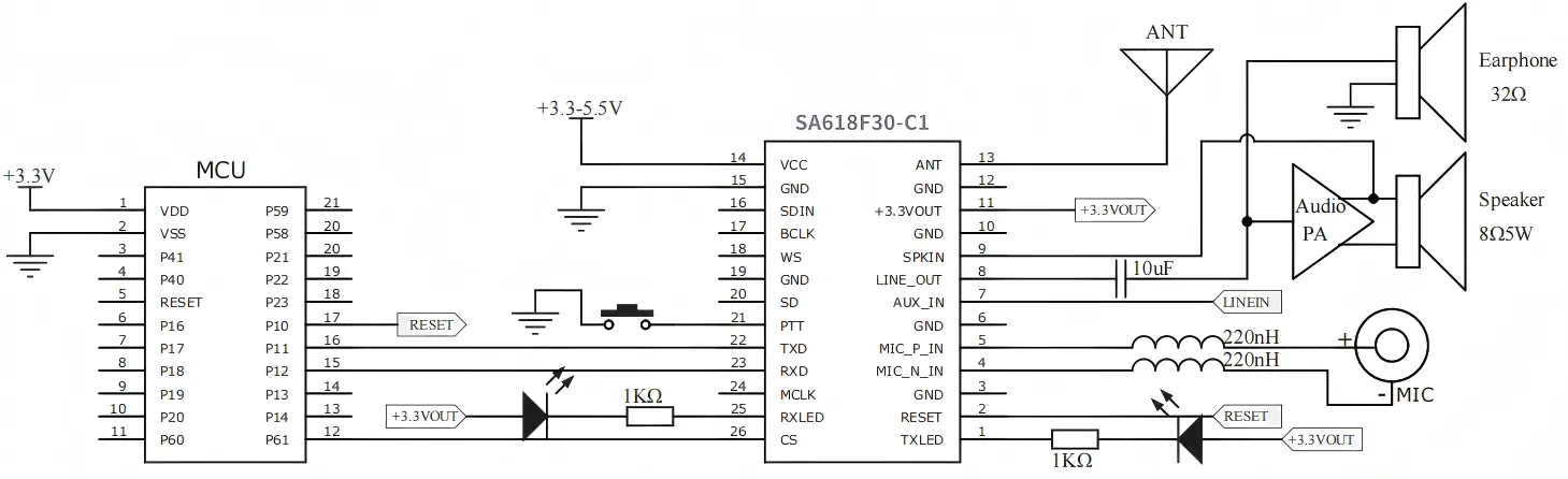
The SA618F30-C1 V3.0 version adds a new SPKIN pin, which significantly enhances the echo cancellation performance. If the customer's product is compact and the microphone is located close to the speaker, we recommend using the V3.0 version as a priority to achieve better voice quality and echo suppression.
Parameter | Test Conditions | Min. | Typ. | Max. | Unit |
Operating voltage | 3.3 | 4.2 | 5.5 | V | |
working temperature | -30 | 25 | 70 | ℃ | |
Current consumption | |||||
Sleep current | 10 | 20 | uA | ||
RX current | @ No audio output | 50 | 55 | mA | |
TX current | 4v,@30dBm | 160 | mA | ||
RF parameter | |||||
Operating frequency | UHF | 410 | 480 | MHz | |
Customizable frequency | 150 | 960 | MHz | ||
Default shipping frequency | UHF ( 1MHz interval) | 440.125 | 455.125 | MHz | |
Transmit power | @5V | 16 | 32 | dBm | |
Bandwidth(BW) | 500 | KHz | |||
Receiving sensitivity | -117 | dBm | |||
Audio parameters | |||||
Modulation sensitivity | 10 | 100 | mV | ||
Receive signal-to-noise ratio(SNR) | 90 | dB | |||
Frequency response | 60 | 3800 | Hz | ||
Audio output(line out) | Load 16 Ω | 40 | mW | ||
8 channels | 160 | 200 | 240 | ms | |
Features
High integration and small size
Applications
Analog input & output application circuit
V2.2 Typical Application Circuit

V3.0 Typical Application Circuit
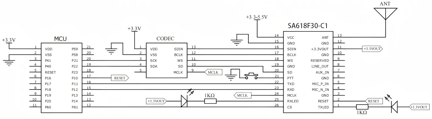
IIS input and output application circuit

Pin NO. | Pin name | I/O | Description |
1 | TXLED | O | Transmitting indicator, connected with external led, turn on by low level output when data or voice is transmitting, (suggest 1K ohm resistor for current limitation) |
2 | RST | I | Module reset pin, externally pull down for more than 5ms will reset the module |
3, 6, 10, 12,15,19 | GND | Ground | |
4 | MIC_N_IN | I | Negative electrode of external microphone, serial connected with 220 nH inductance, refer to below typical circuit. |
5 | MIC_P_IN | I | Positive electrode of external microphone, serial connected with 220 nH inductance, refer to below typical circuit. |
7 | Aux_IN | I | External audio input signal, maximum 1 VRMS |
8 | LINE_OUT | O | External 16-ohm headphones can be connected, requiring an additional LC low-pass filter circuit to eliminate RF interference. Refer to the typical circuit. |
9 | Reserved | Module test pins should be left unconnected by the user. | |
SPKIN | Echo cancellation sampling input, connected to the speaker output. Refer to the Typical Application Circuit (PCB V3.0) for details. | ||
11 | +3.3V Out | O | 3.3v regulator out, maximum 50mA loading |
13 | ANT | Connected with 50ohm Antenna | |
14 | VCC | Power supply ( 3.3 – 5.5V ) | |
16 | SDIN | I | Connected with External I2S device, ( 0 – 3.3V ) |
17 | BCLK | O | |
18 | WS | O | |
20 | SD | O | |
21 | PTT | I | module transmit pin is pulled low to enter transmit mode, with an internal pull-up resistor, defaulting to a high-level output |
22 | TXD | O | Serial transmit pin (voltage 0-3.3V) |
23 | RXD | I | Serial receive pin (voltage 0-3.3V) |
24 | MCLK | O | Connected with External I2S device (0-3.3V) |
25 | RXLED | O | Receiving indicator, connected with external led, turn on by low level output when data or voice received, (suggest 1K ohm resistor for current limitation) |
26 | CS | I | module sleep pin operates at high level for normal function and low level for sleep mode. It has an internal pull-up resistor, defaulting to high level |


Output Power: 1W
Certification: Others
Type: Wireless Audio
Size (mm):39.3*24.0

Output Power: 1W
Certification: Others
Type: Wireless Audio
Size (mm):39.3mm*24mm

Output Power: 160mW
Certification: Others
Type: Wireless Audio
Size (mm):48.1*33.9

Output Power: 1W
Certification: Others
Type: Wireless Audio
Size (mm):57.9mmX36.6mm
Privacy Policy
· Privacy Policy
There is currently no content available
Email:sales@nicerf.com
Tel:+86-755-23080616