 English


Contact us
HOME > PRODUCTS > LORA & LORAWAN MODULES (SPI ) > LORA128X-C1 : 2.4GHZ LONG-RANGE LORA WIRELESS TRAN...
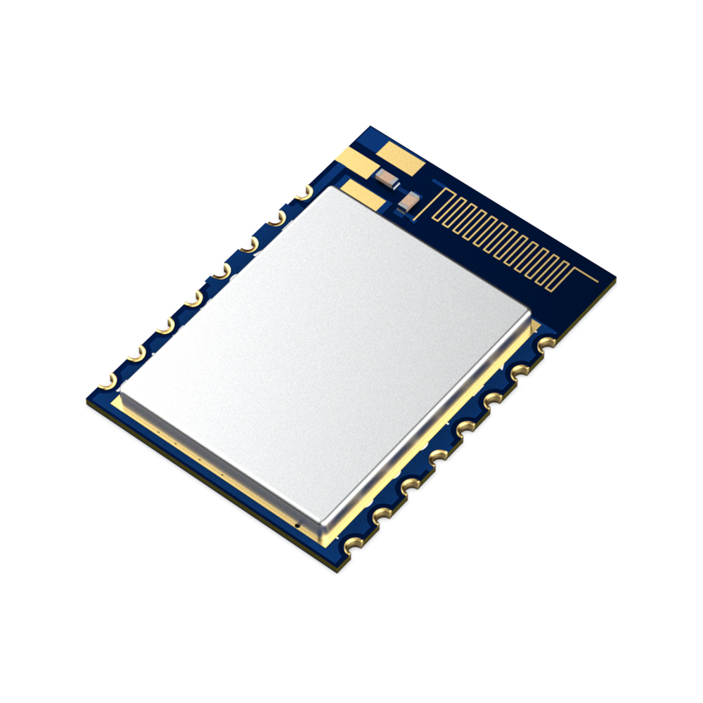

LoRa128X-C1 : 2.4GHz Long-Range LoRa Wireless Transceiver Module For Extended Connectivity
The LoRa128X-C1 series is strictly manufactured and tested using lead-free processes, complying with RoHS and Reach standards.
This series of modules is designed based on the SX1280/SX1281 RF chips from the original US manufacturer Semtech. It utilizes LoRa modulation, effectively addressing the limitation of short communication distances in common 2.4GHz modules. Additionally, the modules integrate "time of flight" functionality for wireless distance measurement applications.
With the high penetration capability of the 2.4GHz frequency band combined with LoRa modulation, these modules offer excellent reception sensitivity and resistance to environmental interference, making them suitable for scenarios requiring long-distance 2.4GHz transmission.

Module | LoRa128X-C1-TIP | LoRa128X-C1-TA | LoRa128X-C1-IP | LoRa128X-C1-A |
Features | Equipped with IPEX Antenna Connector, 0.5ppm Industrial-Grade TCXO Temperature-Compensated Crystal Oscillator | Onboard PCB Antenna, 0.5ppm Industrial-Grade TCXO Temperature-Compensated Crystal Oscillator | With IPEX Antenna Connector, 10ppm Industrial-Grade Crystal Oscillator | Onboard PCB Antenna, 10ppm Industrial-Grade Crystal Oscillator |
★ The following parameters are obtained through testing with a 50-ohm coaxial cable connected to the instrument @VCC=3.3V.
Parameters | Min. | Typ. | Max. | Unit | Condition |
Working Condition | |||||
Working voltage range | 1.8 | 3.3 | 3.7 | V | |
Temperature voltage | -40 | 85 | ℃ | ||
Current Consumption | |||||
RX current | < 11 | mA | @LoRa128x-C1-IP/ LoRa128x-C1-A | ||
< 13 | mA | @LoRa128x-C1-TIP/ LoRa128x-C1-TA | |||
TX current | 50 | mA | @VCC=3.3V,12.5dBm
| ||
Sleep current | < 1 | uA | |||
Frequency range | |||||
Frequency range | 2400 | 2500 | MHz | ||
Data rate | 0.476 | 202 | Kbps | @LoRa | |
260 | 1300 | Kbps | @FLRC | ||
125 | 2000 | Kbps | @FSK | ||
Output power | -18 | 12.5 | dBm | @VCC=3.3V | |
Receiving sensitivity | -132 | dBm | LoRa@0.476Kbps | ||
n Operating Frequency Range: 2400-2500 MHz
n LoRa FLRC FSK Modulation
n Data Transfer Rate: 0.476-202 Kbps @ LoRa
n Maximum Output Power: 12.5dBm
n Sensitivity: -132dBm @ LoRa
n High-Precision Crystal Oscillator (0.5ppm TCXO/10ppm)
n Packet Communication Mode (Receive/Transmit FiFo 256 bytes)
n Operating Voltage Range: 1.8-3.7 V
n Operating Temperature Range: -40~+85°C
Applications
n Wireless Remote Control
n Smart Home
n Toy Control
n Tire Pressure Monitoring
n Health Monitoring
n Tag Reader/Writer
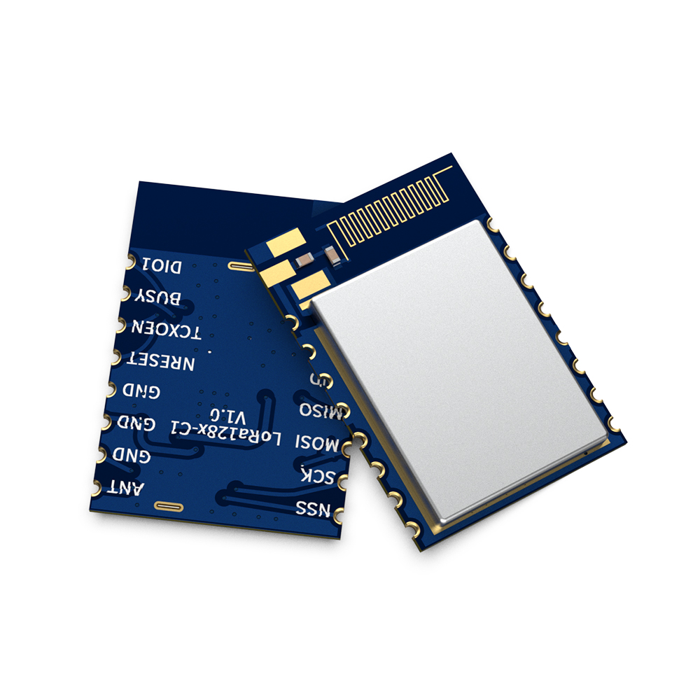
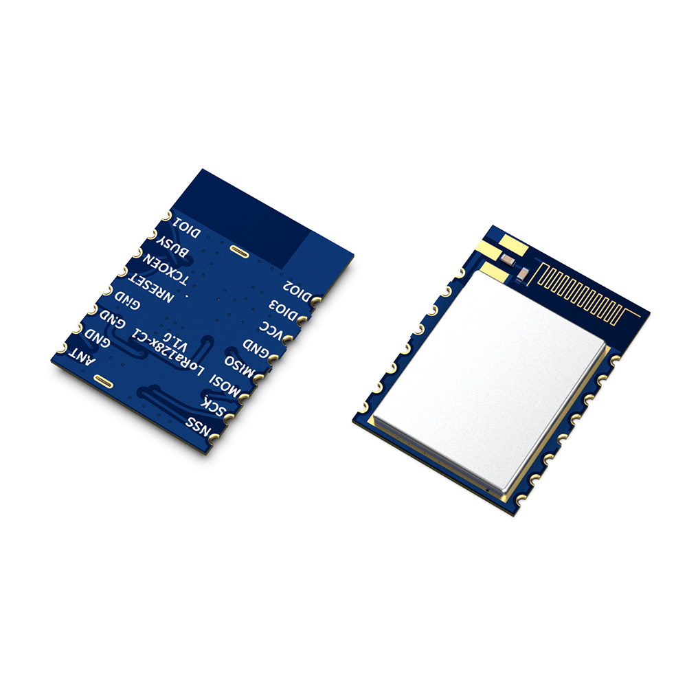
LoRa128X-C1-TIP/LoRa128X-C1-TA:

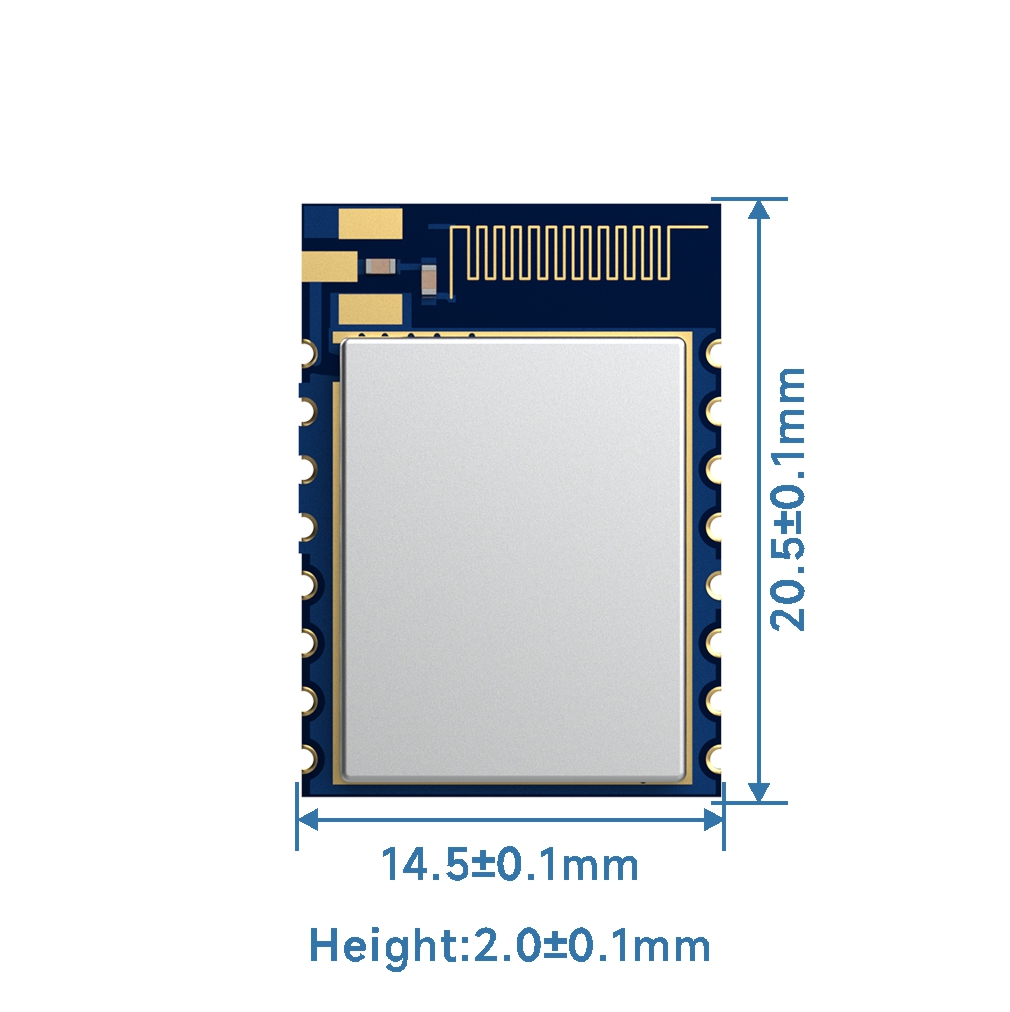
LoRa128X-C1-IP/LoRa128X-C1-A:


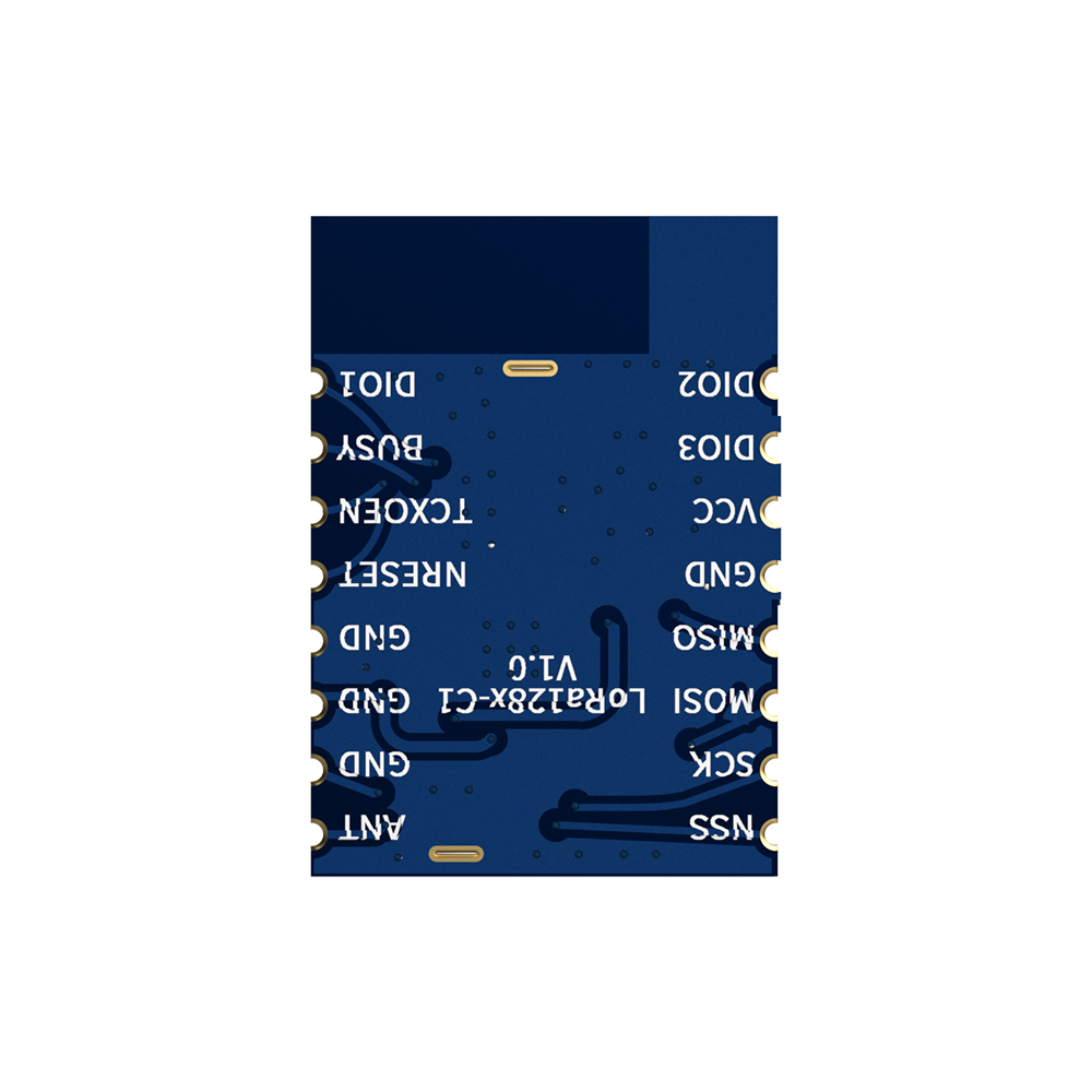
Pin NO. | Pin name | Description |
1 | ANT | Connect with 50 ohm coaxial antenna |
2,3,4,12 | GND | Connected to the negative pole |
5 | NRESET | Chip reset trigger pin, active low |
6 | TCXOEN | Turn on TCXO: 1.Turn TCXOEN pin to high level before reset SX1280;; 2.Delay at least 3ms to wait for the TCXO startup; 3.During the use of the 1280 module, TCXOEN must keep in high level Turn off TCXO (if module needs to enter sleep mode): 1.Call the Set Sleep() function to put the module into sleep mode; 2.Delay for at least 1ms to wait for the module to complete its sleep process; 3.Pull down TCXOEN to disable TCXO; When using a regular crystal oscillator, leave this pin floating. |
7 | BUSY | Status indicator pin (refer to the SX1280/1281 datasheet for details). |
8 | DIO1 | Direct connect chip pins, configurable as general-purpose I/O (function details can be found in the SX1280/1281 data sheet). |
9 | DIO2 | Direct connect chip pins, configurable as general-purpose I/O (function details can be found in the SX1280/1281 data sheet). |
10 | DIO3 | Directly connected chip pins, configurable as general-purpose I/O (function details can be found in the SX1280/1281 data sheet). |
11 | VCC | Connect the positive power supply (1.8-3.7V). |
13 | MISO | SPI Output for SPI data |
14 | MOSI | SPI Input for SPI data |
15 | SCK | Serial clock for SPI interface |
16 | NSS | Module chip select pin |
