Contact us
HOME > PRODUCTS > WALKIE TALKIE MODULES > DMR858S : 5W EMBEDDED DMR TIER II WALKIE TALKIE MO...
DMR858S : 5W Embedded DMR Tier II Walkie Talkie Module
- DMR858S is an ALL-IN-ONE DMR 5W professional walkie talkie module. It combined analog and DMR Tier II walkie talkie function. This product is compatible with DMR radio with Moto AMBE++ and all the analog walkie talkie in the market. DMR858S is easy to use , which embedded DSP processor , DMR encoder/decoder, RF / Audio Amplifier , PTT, Microphone, 16 Channel switch, Volume adjustment all on board. Just connected with power supply and speaker, it build a 5W professional DMR walkie talkie. DMR858S has long range and good voice quality. Special heat sinks are designed specially to guarantee long time talking.
- The digital intercom supports the following functions in DMR mode:
- SMS sending function, support pass-through and SMS application;
- Voice encryption function, SMS encryption function;
- Calling and called prompts.
| Parameters | Condition | Min | Typ | Max | Unit | ||
| Power Supply | 3.6 | 4.0 | 8.4 | V | |||
| Working temperature | -20 | 25 | 60 | ℃ | |||
| Frequency Range | @UHF | 400 | 470 | MHz | |||
| @VHF | 134 | 174 | MHz | ||||
| @350 | 320 | 400 | MHz | ||||
| Serial baud rate | 57600 | bps | |||||
| Current Consumption | |||||||
| Sleep current | @CS pulled low for 3 seconds | 1 | mA | ||||
| RX Current | 170 | mA | |||||
| TX current (High power)-DMR | @VCC=4.0V,2w | 650 | mA | ||||
| @VCC=8V,5w | 1000 | mA | |||||
| TX current (Low power)-DMR | @VCC=4.0V,0.5w | 400 | mA | ||||
| @VCC=8.0V,1w | 460 | mA | |||||
| TX current (High power)-Analog | @VCC=4.0V,2w | 1200 | mA | ||||
| @VCC=8V,5w | 1600 | mA | |||||
| TX current (Low power)-Analog | @VCC=4.0V,0.5w | 700 | mA | ||||
| @VCC=8V,1w | 800 | mA | |||||
| Analog Rx Parameters | |||||||
| Rx sensitivity (Analog) | @12dB SINAD | -120 | dBm | ||||
| S/N | @1.5K deviation | 40 | dB | ||||
| Adjacent channel selectivity | 12.5KHz offset | 62 | dB | ||||
| Inter modulation Rejection | 12.5KHz offset | 63 | dB | ||||
| Blocking immunity | Interference frequency interval >1M | 88 | dB | ||||
| Audio amplitude(line out) | F0=1KHz | 0.2 | 130 | 460 | mV | ||
| Output impedance of audio(SPK) | 8 | Ohm | |||||
| Audio distortion | F0=1KHz | 5 | % | ||||
| Audio response | 300Hz | 8 | dB | ||||
| 500Hz | 6 | ||||||
| 1KHz | 0 | ||||||
| 2KHz | -6 | ||||||
| 3KHz | -12 | ||||||
| DMR Rx Parameters | |||||||
| BER(DMR Mode) | @ -117dBm | 4 | % | ||||
| Adjacent channel selectivity(ACS) | Offset:+12.5KHz | 60 | dB | ||||
| Offset:-12.5KHz | |||||||
| Inter modulation Rejection | Offset:+50/100KHz | 63 | dB | ||||
| Offset:-50/100KHz | |||||||
| Blocking immunity | Offset:+/-1MHz | 87 | dB | ||||
| Offset:+/-5MHz | |||||||
| Analog Tx Parameters | |||||||
| Max Freq deviation | 12.5KHz deviation(N) | 2.2 | 2.5 | KHz | |||
| 25KHz deviation(W) | 4.5 | 5 | KHz | ||||
| Sensitivity | deviation: 1.5KHz/2.5KHz | 4 | 7 | 10 | mV | ||
| Audio distortion | deviation: 1.5KHz/2.5KHz | 1 | 5 | % | |||
| Modulation characteristic | 300Hz | -13 | -11 | -9 | dB | ||
| 500Hz | -9 | -6 | -5 | dB | |||
| 1KHz | -3 | 0 | 1 | dB | |||
| 2KHz | 3 | 6 | 7 | dB | |||
| 3KHz | 3 | 7 | 11 | dB | |||
| CTCSS deviation | 350 | 400 | 600 | Hz | |||
| Output power of adjacent channel | 12.5KHz offset | -60 | -63 | dBc | |||
| SNA | 1.5KHZ/2.5KHz | 38 | 40 | 50 | dB | ||
| DMR Tx parameters | |||||||
| Frequency error | 0.5 | ppm | |||||
| 4FSK Tx BER | ≤1×10⁻⁴ | ||||||
| Output power of adjacent channel | +/-12.5KHz | ≤-55 | dB | ||||
| Output power of next adjacent channel | +/-25KHz | ≤ -65 | dB | ||||
| Type | DMR walkie talkie |
| Output Power | 5W |
Features of DMR Walkie Talkie Module DMR858S
- UHF band frequency:400~470 MHz
- VHF band frequency:134~174MHz
- 350 band frequency:320-400MHz (3 frequency bands are optional)
- 6~8 Km in open area
- Max power output to 5W Low power to 1W
- Sensitivity up to:-120dBm
- Less than 2% BER @ -117dBm
- TX/RX frequency set separately
- Bandwidth for analog:12.5 / 25 KHz Bandwidth for DMR:6.25KHz
- DMR / Analog walkie talkie
- SMS transmission and reception
- Built-in EEPROM, data saved even powered off
- Low power consumption in sleep mode
- DMR Tier II
- Tail sound elimination automatically
- Embedded design for handheld product
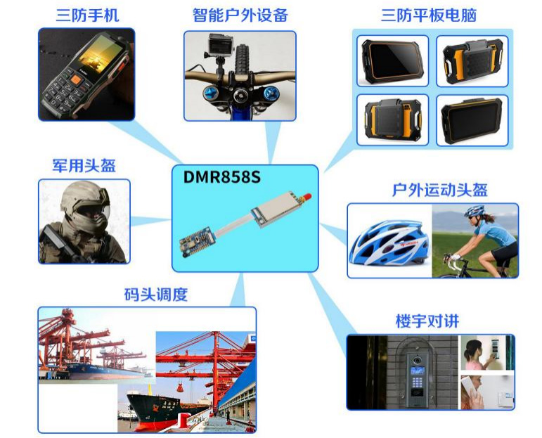
Application of DMR Walkie Talkie Module DMR858S


DMR858S Functional Board

| Pin No | Definition | I/O | Description |
| 1,2,4 | GND | Ground | |
| 3 | MIC_IN | I | Microphone input |
| 5 | UART-RX | I | Connected with UART-TX of external device |
| 6 | UART-TX | O | Connected with UART-RX of external device |
| 7,13 | GND | Ground | |
| 8 | CS | I | Sleep: 0 ; working: 1 (high level or leave open) |
| 9 | PTT | I | TX: 0, RX: 1 |
| 10 | LINE_OUT | O | Line out for voice |
| 11 | T/R | O | TX/RX indicator, 1: TX , 0: RX |
| 12 | SPKEN | O | Valid signal indicator, 1: signal valid, 0: No valid signal received. This pin can be used to drive ecternal voice amplifier. 1: on, 0:off |
| 14,15 | +3.3 V | 3.3V output,maximum 50mA loading | |
| 16,17,18,19 | +VCC | VCC (3.3V-9V) | |
| 20 | GND | Ground |
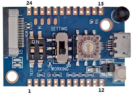
DMR858S-PJ (Control Board )

| Pin No. | Definition | I/O | Description |
| 1 | VCC | VDD (connected to Pin 19 of function board) | |
| 2,4 | GND | Ground | |
| 3 | CS | I | Connect to CS of the function board |
| 5 | PTT | I | Connect to PTT of the function board |
| 6 | LINE_OUT | O | Connect to Line Out of the function board |
| 7 | 8 | I | Frequency channel selection,( 16 channels ), The frequency channlel can be selected either by the onboard rotary switch or these pads input. Turn to channel 0 or remove the rotary switch if user want to control the channel with these pads. |
| I | 8 :the maximum bit, | ||
| I | 4: the 3rd bit, | ||
| I | 2: the 2nd bit; | ||
| I | 1: the least bit for example : | ||
| I | 8421 encoding: | ||
| I | 0000: channel 0, | ||
| I | 0001: channel 1 | ||
| I | 0010: channel 2 | ||
| 8 | 4 | I | 0011 :channel 3 |
| 9 | 2 | I | … |
| 10 | 1 | I | 1111 : channel 15 |
| 11 | SPKN | o | Connected with Speaker: 8 Ohm 2W |
| 12 | SPKP | o | |
| 13,15,17 | GND | Ground | |
| 14 | SET | I | Setting mode (0: setting mode , 1: normal mode ) |
| 16 | MIC_IN | I | Connect to Mic_IN of the function board |
| 18 | TXD | O | Connect to TXD/RXD of the function board |
| 19 | RXD | T | |
| 20 | +3.3V | 3.3V output,maximum 50mA loading | |
| 21 | SPKEN | Connect to SPKEN of the function board | |
| 22 | NC | NC | |
| 23 | H/L | I | Output power control, 0: low, 1: high |
| 24 | GND | Ground |


 English


